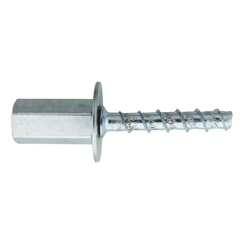
Concrete screw W-BS Compact type I
Concrete screw W-BS/I Compact
CSCR-(W-BS/I-COMPACT)-WS13-M8/M10-6X40
Art.-no. 5929570601
EAN 4061975594495


Register now and access more than 60,000 products
- Quick and easy installation without the need for a tangential impact screwdriver
- Time and cost-saving assembly
- Extremely flexible in application (step thread M8/M10)
- Can be assembled by hand
- ETA-15/0091 for anchors in a redundant non-structural system made from concrete
- Fire resistance: R30, R60, R90, R120; Technical Report TR020
- The W-BS Compact can be mounted by hand
- If a cordless drill is used for assembly, it is recommended that at least five preliminary tests are performed on location to ensure the correct drill driver setting and to prevent over-tightening of the W-BS Compact. It is recommended that you start with the drill driver's lowest torque setting and increase it if necessary
- A tangential impact driver must not be used for assembly
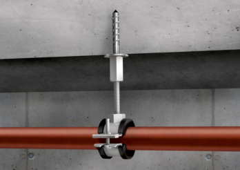 Pipe suspensions with threaded rods/pieces
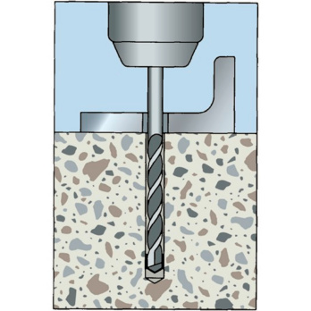
Create the drill hole
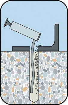
Clean the drill hole
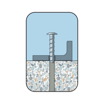
Position anchor
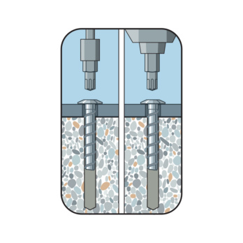
Screw in anchor
- ETA-15/0091 for anchors in a redundant non-structural system made from concrete
- Fire resistance: R30, R60, R90, R120; Technical Report TR020
Datasheets(X)
- Multiple attachment of non-load-bearing systems with European Technical Assessment
- The simplest solution for suspensions with threaded rods of size M8 and M10, suitable for e.g. suspended ceilings substructures, suspended cables and pipe lines, HVAC installations, single pipe and ventilation installations etc.
- Use in cracked and non-cracked concrete ≥ C20/25
- W-BS Compact (zinc plated steel) may only be used in dry indoor room conditions
 | |
Type description | W-BS Compact type I |
Anchor size | 6 mm |
Thread diameter | 7 mm |
Anchor length (l) | 40 mm |
Head type | Hexagon head |
Max. attachment height (t fix) | 15 |
Drill hole depth (h 1) | 28 mm |
Surface | Zinc plated |
Material | Steel |
Embedding depth (h nom) | 25 mm |
Minimum component thickness (h min) | 80 mm |
Connection thread | IT M8, IT M10 |
Effective anchoring depth (h ef) | 25 mm |
Through-hole in the component to be connected (d f) | 8 mm |
Drill cutting diameter (d cut) | 6.35 mm |
| Installation parameters | ||
| Anchor size | 6 | |
| Axis distance | scr,N [mm] | 200 |
| Edge spacing | ccr,N [mm] | 150 |
| Minimum component thickness | hmin [mm] | 80 |
| Length of anchor in drilled hole | hnom ≥ [mm] | 25 |
| Fastening height | tfix [mm] | L-hnom |
| Nominal drill ∅ | d0 [mm] | 6 |
| Drill cutting ∅ | dcut ≤ [mm] | 6,35 |
| Drill hole depth | h1 ≥ [mm] | 28 |
| Through hole in the component being connected | df ≤ [mm] | 8 |
| Mounting torque | Tinst [Nm] | 10 |
| Performance data (for hnom≥ 25) | ||
| Anchor size [mm] | 6 | |
| Multiple attachment of non-load-bearing systems in concrete1) | Fadm [kN] = C20/25-C50/60 | 0,43 |
| Permissible load under fire load2) | R30; Fperm [kN] | 0,27 |
| R60; Fperm [kN] | 0,27 | |
| R90; Fperm [kN] | 0,22 | |
| R120; Fperm [kN] | 0,17 | |
| Permissible bending torque | Mperm. [Nm] | 7,9 |
| 1) The partial safety factors of the resistances regulated in the approval and a partial safety factor of the actions of γF = 1.4 have been taken into account. For information on combining tensile and shear loads, on the influence of the edge distance, and on anchor groups, please refer to the European Technical Approval Guidelines (ETAG), Annex C. 2) The partial safety factors for the load capacity when exposed to fire of γM,fi = 1.0, as recommended in the approval, and the partial safety factor of the action of γF = 1.0 have been taken into account. | ||
Select RAL-colour code
!! NOTE: On-screen visualisation of the colour differs from real colour shade!!


